 University of PisaBScAcademicMay – Jul 2020
Manufacturing Process Design of a Wankel Engine
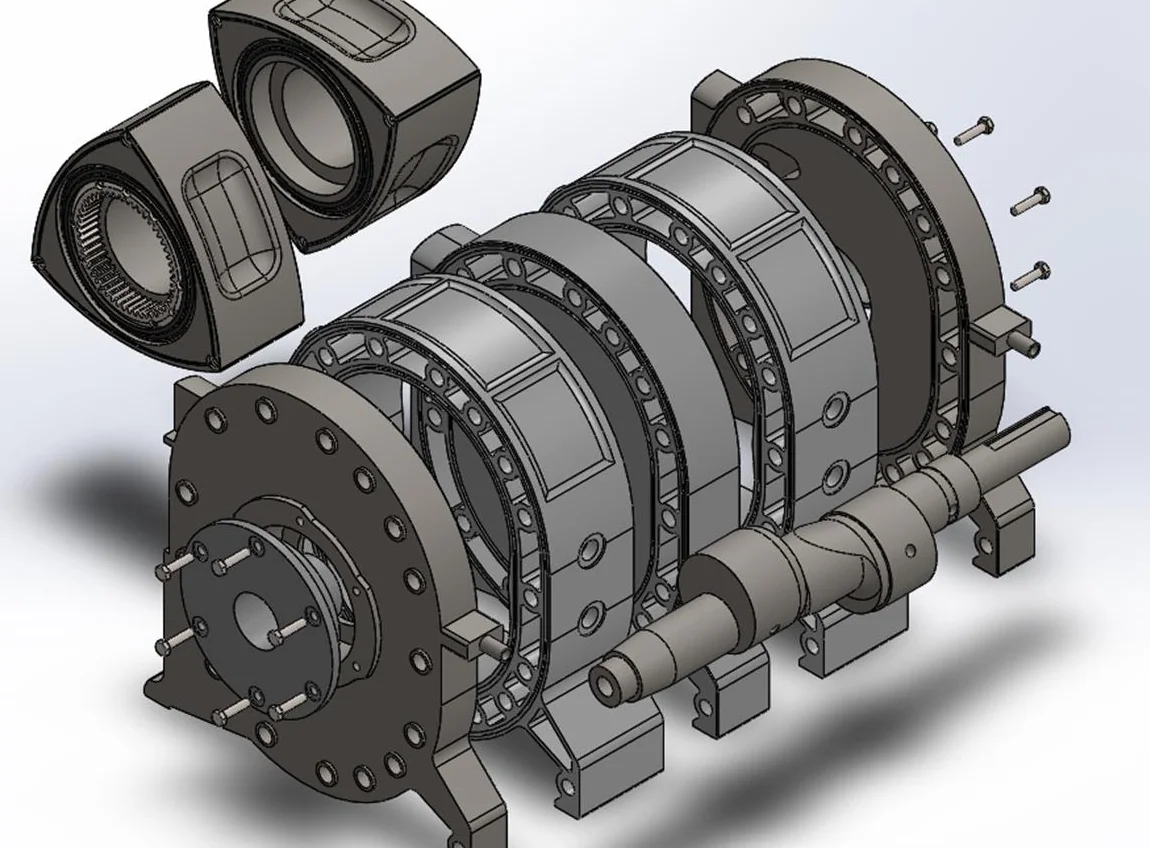
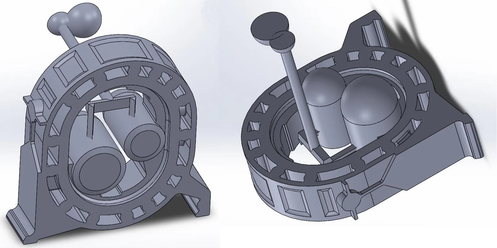
Manufacturing plan for a twin-rotor Wankel engine: sand casting of the rotor housing checked with SOLIDCast, CNC turning of the eccentric shaft with its part program, and machining of the stationary gear.
Three parts, three processes
A team project on how to manufacture a twin-rotor Wankel engine. We focused on three parts, each with its own process: the cast-iron rotor housing, the eccentric shaft and the stationary gear.
Sand, simulation and G-code
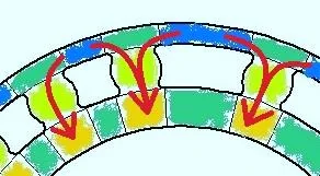
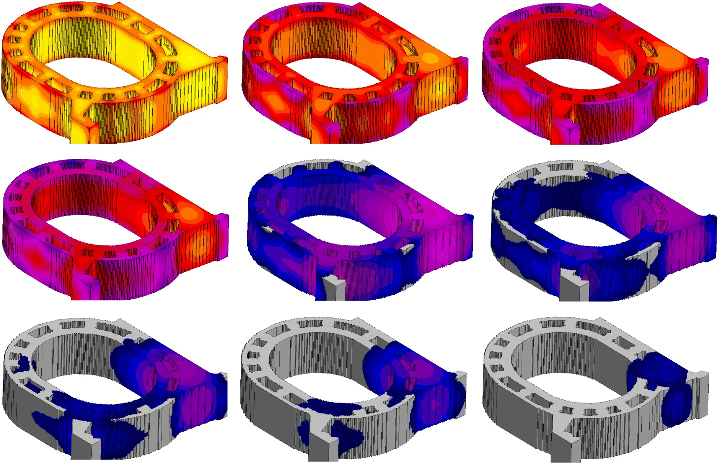
The rotor housing is a sand casting in grey iron. We chose the parting plane, allowances, cores and draft angles, checked the solidification with the modulus method and SOLIDCast, then sized the risers and the gating system.
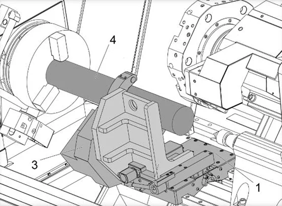
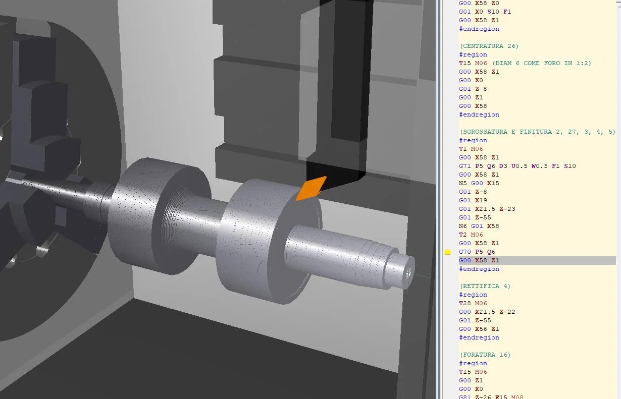
The eccentric shaft is turned on a twin-spindle CNC lathe around three axes, with a fixture designed for the eccentrics. The part program was written and checked in CNC Simulator, together with tools, cutting data, power and machining times.
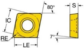
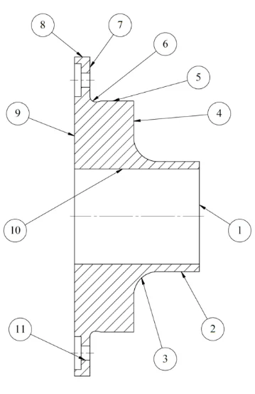
The stationary gear, in 39NiCrMo3, is turned and drilled from bar: phases and set-ups were planned to move the part as little as possible, with tools and cutting data taken from the Sandvik Coromant and WNT catalogues.
A full process plan for each part
Each part ended with a complete process plan: material, machines, tools and phases, with drawings made in SolidWorks. The simulation confirmed where the casting solidifies last, so the risers sit exactly there and shrinkage defects stay out of the part.
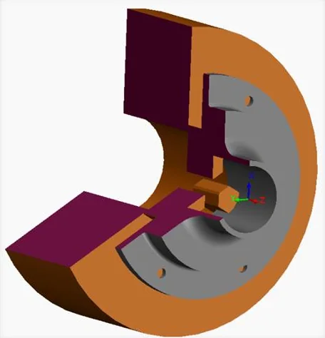
For the stationary gear, every surface to machine was numbered on the drawing and assigned to a phase; the internal clamping lets most of it be turned in a single set-up.
Loading the report…
Book a call: the calendar opens right here.
Book a call
Pick a day and time for a Google Meet video call
Choose a day
No free times on this day.
Booked!